Fluid Control Equipment
PowerTrap® (Mechanical Pump with Built-in Trap)
GT Series
Eliminates stall caused by insufficient differential pressure
When the steam pressure in the heat exchanger is lower than the outlet side pressure (back pressure), condensate is not discharged from the steam trap and remains in the equipment. This phenomenon is called "stall phenomenon" and can cause various problems.
The stall phenomenon is explained in detail in Stall Phenomenon Part 1 (Causes and Problems) and Stall Phenomenon Part 2 (How to Resolve Stall) in Steam Theory.
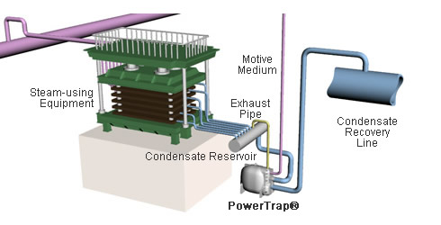
General configuration
Precautions for use and selection
Although the PowerTrap reduces condensate retention in the equipment heat exchanger, it cannot guarantee the elimination of equipment and piping problems (*1) such as water hammer, nor can it guarantee improved operational performance (*2) such as improved controllability.
To ensure that these problems and issues are resolved, it is necessary to identify the causes in advance. Comprehensive diagnosis (for a fee) by TLV engineers is available as a cause investigation, contact your local TLV representative for details.
- *1 When the piping route in the heat exchanger is narrow and condensate flow is obstructed by surface tension, or when steam leakage from the piping layout or surrounding valves is the cause.
- *2 Controllability of control valves and temperature controllability of unheated and cooled materials, etc.
Piping example
The piping diagrams shown here are intended to provide an overview of the system and are not intended for installation construction purposes.
Example of standard piping for heat exchanger with GT10
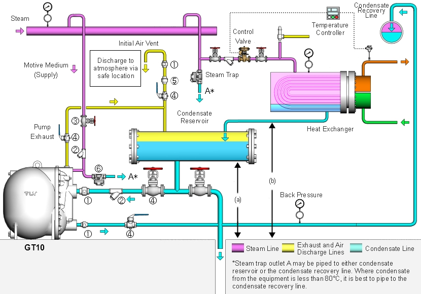
| (1) | Check valve PowerTrap is supplied with an inlet/outlet check valve. |
(4) | Globe valve or ball valve |
| (2) | Strainer 40 mesh or larger | (5) | Air vent |
| (3) | Globe valve or needle valve | (6) | Steam trap |
| (a) | Filling head | (b) | Height to equipment condensate outlet |
|
Caution
|
|||