- Home
- Steam Resources
- Steam Theory
- Group Trapping
Steam Trap Problems
Group Trapping
Collecting condensate from several sections of steam-heated equipment into one condensate line that discharges into a single trap is a practice know as 'Group Trapping'. Group trapping is typically discouraged because it can cause pressure imbalance, which leads to problems such as waterlogging and water hammer damage in the equipment. Instead, it is generally recommended that each and every section of steam equipment have its own steam trap.
| Group Trapping is Typically Not Recommended | |
|---|---|
|
|
|
| Group Trapping | Individual Trapping |
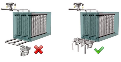
For instance, a heat exchanger that is divided into three sections such as the one above should not be drained using a single steam trap because the condensing load on the first section is larger than the last section, leading to pressure imbalance. Rather, three traps should be installed to allow condensate drainage directly from each individual section of the heat exchanger.
Why Group Trapping Is Discouraged
As an example, consider a heat exchanger comprised of finned tube coils. The fins are heated by steam flowing through piping connected together through a header. Several of these units are often installed in a row to increase the heat transfer surface and heating capacity. While it is possible to consider the entire piece of machinery as whole, from the standpoint of condensate drainage each individual section is a separate heat exchanger that collects condensate.
The amount of condensate produced differs from section to section because of load differences between the initial pre-heat section compared to subsequent intermediate and final heating sections. The initial section typically has the highest load and therefore will encounter the highest pressure drop. Accordingly, the final section typically has the lowest load, and will encounter the lowest pressure drop. In such a case, the initial section’s outlet pressure is lower than the final section’s outlet pressure, which creates a kind of “short circuit” of highest pressure discharged from the final section.
The intermediate and initial heating sections have greater pressure drops, so when group trapping is used, there is a pressure imbalance. That imbalance requires that condensate back-up into the coil to create sufficient “head pressure” to drain. So, when condensate from each section is discharged through a single trap, differences in load and subsequent outlet pressures will cause waterlogging and water hammer damage, coil stratification, uneven drainage, and corrosion damage. While an unnecessary added maintenance expense, the worst result is that uneven heating reduces production quality and yield.
For more information on water hammer, please refer to the following article:
| Issues Caused by Group Trapping |
|---|
|
|
| Waterlogging and subsequent problems such as uneven heating, corrosion, and damage from thermal shock or water hammer can occur when a single trap is used to discharge condensate from several sections of machinery. |
When Group Trapping is already installed
Some machinery is constructed in such a way that trap numbers are limited because of difficult configuration, lack of space or to reduce costs. In such cases it might be difficult to retrofit or install a trap to discharge condensate from each section of the equipment. Still, individual trapping is the recommended first choice for best performance whenever it can be accomplished.
However, group trapping is still used in certain installations such as:
- Air heaters
- Multi-platen presses
- Corrugated cardboard double facers
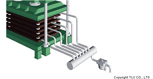
If equipment is constructed in such a way that group trapping is already installed and it is not possible to trap individually, then sometimes an equalizing drain header will be installed before the trap. This drain header must have a large enough vapor space capacity to enable pressure balancing which will help condensate drainage.
| Platen Press with Drain Header |
|---|
|
|
| Problems Related to the Installation of a Drain Header |
|---|
|
|
| * The pressure gauges were added to help illustrate the differences in pressure between the piping and drain header. Installing a drain header may help some condensate flow, but most likely causes higher radiation steam loss, larger and more expensive pipes and valves, and must be a near-perfect installation to avoid coil stratification. Drain headers cannot resolve problems related to uneven pressure within piping, and this is why individual trapping remains the preferred method. |
This is not recommended if individual trapping can be done, and there are several instances where results can be less than desirable. For example, if the drain pipes feeding the header are not always gravity draining downward (there should be no lifts) and if they are not large enough to allow balancing within them, then steam from another section which has higher pressure than the section with a higher load will cause back-up.
A drain header only has a chance to work if the inlet piping supplying it is large enough to allow equalization by condensate draining down the piping sides with steam balancing through the center of the outlet. If there is the chance that the inlet piping supplying the drain header closes off the line with condensate, then condensate will back-up leading to coil stratification, uneven heating, and other waterlogging issues may develop.
While installing a sufficiently large header can help resolve some drainage problems related to group trapping of condensate equipment – provided the above conditions are met – the most effective way to optimize performance of a heat exchanger is to individually trap sections that may have unique pressures from adjoining sections, even if the steam supply is common.
Summary
When installing traps on machinery, group trapping should be avoided as much as possible. If group trapping is unavoidable, it is important to verify with the equipment manufacturer the proper way to drain condensate from equipment. Also, for the reasons stated above, when equipment is already configured to drain condensate through several steam traps, it is highly recommended to maintain this configuration for optimum process performance and efficiency.