- Home
- Steam Resources
- Steam Theory
- Traps and Orifices Part 1
Basics of Steam Traps
Traps and Orifices Part 1
The word ‘orifice’ literally means an opening. For TLV steam traps, the term orifice is used to refer to the opening or passage through the valve seat.
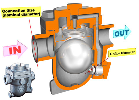
The diameter of an orifice is much smaller than the inner diameter of the connected piping. For example, the orifice diameters available for the J3X Free Float® steam trap are only approx. 2-3 mm [⅛ inch] or less. This is because the size of the orifice depends on the steam trap’s body size and the operating pressure differential, not the size of the connection port.
Why is the Diameter of an Orifice So Small?
While a Free Float® steam trap with a nominal connection size of 15mm [½ inch] is typically connected to piping with an inner diameter of 15mm [½ inch], the diameter of the orifice may only be around 2-3mm [⅛ inch] or less.
This is because although piping is generally sized for two-phase flow (condensate with steam vapor), the orifice only needs to be sized for the condensate volume. For example, with a pressure differential of 0.2 MPaG [30 psi] ], a 2-3mm [⅛ inch] orifice can discharge approximately 350 kg/h [770 lb/h] of condensate. This would be sufficiently large for condensate drainage based on the estimated steam consumption of small-scale equipment that has a 15mm [½ inch] diameter condensate outlet. Some traps have a slightly larger discharge capacity because condensate can also be discharged through their thermostatic air vent.
It follows, of course, that a larger size orifice would allow the trap to have a greater discharge capacity. However, for the trap to operate at the same pressure differential, this would require a proportionally larger float, which would in turn increase the size of the trap body.
Discharge Capacity and Nominal Connection Size
In the case of most mechanical type traps, it is the size of the orifice, not the size of the connection port, that determines the discharge capacity. There is no direct relationship between connection size and discharge capacity. Taking a look at the above data sheet (for J3X Free Float® steam trap), it can be seen that different connection piping sizes (i.e. 15 mm, 20 mm, and 25 mm) all have the same discharge capacity for a given orifice size.
As mentioned earlier, a larger size orifice could allow a trap to have a greater discharge capacity. However, this would require a proportionally larger size float for the same pressure differential, which increases the size of the trap body. In short, this means that in order to design a trap with sufficient capacity, the appropriate orifice size and float diameter must be determined.
Valve opening and closing forces play a role in determining the size of the orifice and float. For a more detailed explanation of this, see Traps and Orifices Part 2.