- Home
- Steam Resources
- Steam Theory
- Overall Heat Transfer Coefficient
Basics of Steam
Overall Heat Transfer Coefficient
The overall heat transfer coefficient, or U-value, refers to how well heat is conducted through over a series of resistant mediums. Its units are the W/(m2°C) [Btu/(hr-ft2°F)].
Steam vs. Hot Water
The following article demonstrates how to calculate and compare the U value for the heat transfer of steam and hot water through different types of mediums, including film coefficients and the actual wall material itself.

The overall heat transfer coefficient is influenced by the thickness and thermal conductivity of the mediums through which heat is transferred. The larger the coefficient, the easier heat is transferred from its source to the product being heated. In a heat exchanger, the relationship between the overall heat transfer coefficient (U) and the heat transfer rate (Q) can be demonstrated by the following equation:

where
A = heat transfer surface area, m2 [ft2]
U = overall heat transfer coefficient, W/(m2°C) [Btu/(hr-ft2°F)]
ΔTLM = logarithmic mean temperature difference, °C [°F]
From this equation it can be seen that the U value is directly proportional to Q, the heat transfer rate. Assuming the heat transfer surface and temperature difference remain unchanged, the greater the U value, the greater the heat transfer rate. In other words, this means that for a certain heat exchanger and product, a higher U value could lead to shorter batch times and increased production/revenue.
Calculating the U-value
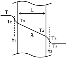
Several equations can be used to determine the U value, one of which is:

where
h = convective heat transfer coefficient, W/(m2°C) [Btu/(hr-ft2°F)]
L = thickness of the wall, m [ft]
λ = thermal conductivity, W/(m°C) [Btu/(hr-ft°F)]
| Heat transfer through a metal wall |
|---|
|
|
In the case of creating hot water for example, heat transfer basically occurs from fluid 1 (source of heat) through a conductive solid (metal wall) to fluid 2 (water, the product being heated). However, film resistance must also be considered. That is why the convective heat transfer coefficient (h), sometimes referred to as the film coefficient, is included when calculating heat transfer between a fluid and a conductive wall.
Additionally, in certain unique applications such as pharmaceutical or biotechnology process heating, that heat transfer can occur through several layers of wall material. In such instances, the above equation can be adapted by incorporating each layer of the solid’s thickness (L) divided by its thermal conductivity (λ).
To facilitate example calculations below, the following values may be used as a reference for the convective heat transfer coefficients:
| Fluid | Convective heat transfer coefficient (h) |
|---|---|
| Water | about 1000 W/(m2 °C) [176 Btu/(hr-ft2 °F)] |
| Hot Water | 1000 – 6000 W/(m2 °C) [176 - 1057 Btu/(hr-ft2 °F)] |
| Steam | 6000 – 15000 W/(m2 °C) [1057 - 2641 Btu/(hr-ft2 °F)] |
Example comparing effect on U of different heat sources, steam or hot water
Two carbon steel (λ = 50 W/(m °C) [28.9 Btu/(hr-ft °F)]) jacketed kettles with an inner wall thickness of 15mm [0.049 ft] are used to heat water. One uses hot water as the heat source, while the other uses steam. Assuming heat transfer coefficients of 1000 W/m2 °C [176 Btu/(hr-ft2 °F)] for the water being heated, 3000 W/m2 °C [528 Btu/(hr-ft2 °F)] for hot water, and 10000 W/m2° C [1761 Btu/(hr-ft2 °F)] for steam, let's calculate the U values for both heating processes.
Carbon Steel Jacketed Kettle – Comparing Hot Water vs. Steam Heat Source
Hot water:

Steam:

In this case, steam provides a calculated U-value improvement of 17%.
Now imagine that the same kettle transfer wall is also lined with glass 1mm [0.0033 ft] thick (λ = 0.9 W/(m °C) [0.52 Btu/(hr-ft °F)]). Including these values into the above U-value equation provides the following results:
Glass-Lined Jacketed Kettle – Comparing Hot Water vs. Steam Heat Source
Hot water:

Steam:

In this case of additional resistance to conductivity, the U-value is still improved, but only by 9%; and this demonstrates how a poor thermal conductor such as glass can greatly interfere with heat transfer.
So for certain heat exchange equipment such as a carbon steel kettle, changing the heat source from hot water to steam can potentially improve the U-value and heat transfer significantly if the wall material is highly conductive. However, the same dramatic effect is not expected in instances where a heat exchanger with several wall layers including layers of material that are not highly conductive (such as a glass-lined kettle) is used.
Nevertheless, some processes require a certain wall material, such as glass lining, to prevent reactivity with the product. Even so, the heat transfer rate may still be improved in such circumstances by changing the heat source from hot water to steam to optimize production.
Advanced Understanding
Fouling
Fouling of the wall material surface can represent an additional barrier to heat transfer. This problem can occur on both the heating medium side and the product side for multiple reasons. Some causes can be particle deposits on the heating side, and excessively high or low temperatures on the product side.
For example, steam pressure is sometimes raised to create the necessary pressure to push condensate through the outlet control valve on a level pot. However, with an increase in pressure within the heat exchanger, steam temperature rises accordingly, and this excessive heat can cause increased fouling on the product side. Conversely, if condensate is allowed to accumulate within equipment, fouling can be caused on the heating side by the debris entrained in the pooled condensate, and on the product side by lower temperatures that cause the product to cake onto the surface when required product viscosity is not maintained.
Fouling can be added to the above equation by including the ratio of its thickness (LF) over its conductivity (λF), in the same manner as the glass-lining was added above, but is typically incorporated into and expressed as a fouling factor for an exchanger that has been “in-service”. Commonly, the calculations to compare reduction in U are for clean versus in-service duty.


