- Home
- Steam Resources
- Steam Theory
- Best Practices for Condensate Removal on Steam Lines
Steam Distribution
Best Practices for Condensate Removal on Steam Lines
The role of steam distribution lines is to reliably supply steam of the highest reasonable quality to the steam-using equipment. In order for this to be achieved, condensate must be removed quickly and efficiently through steam traps installed in proper condensate discharge location (CDL) installations.
Steam traps can't, however, simply be installed any which way and forgotten. There are certain guidelines to follow when installing them on steam lines. To ensure that steam traps operate properly, trap installation methods must be carefully respected and installation locations carefully chosen.
The flow of steam is typically much faster in steam distribution piping than in equipment and can reach speeds of over 30 m/s (100 ft/s). At these speeds, when the cross-sectional area of a pipe section is completely filled by water, slugs of condensate can be carried through the piping at high velocity causing water hammer, which can cause personal injury as well as damage piping, valves, and equipment. The higher flow velocities in steam lines must therefore also be taken into account during decisions regarding location and design of trap installations.
The following four "Best Practices" are guidelines to help ensure the smooth discharge of condensate on steam lines and to prevent the occurrence of typical steam system problems such water hammer and air binding.
Best Practice #1: Choose Trap Locations Carefully
Even in cases where a steam distribution piping run is set in a straight line, steam traps should always be installed at least every 30 to 50 meters (100 to 160 ft), and at the bottom of risers or drops. Special care must also be taken to install steam traps in locations where there is a chance of condensate pooling so that condensate does not close off the cross-sectional pipe area, possibly causing it to be propelled at exceptionally high velocity.
Steam traps should be installed in the following situations:
| Every 30 to 50 meters (100 to 160 feet) |
|---|
|
|
| Traps should be installed at 30 to 50 meter (100 to 160 feet) intervals on a steam line. |
| In Front of Pressure Reducing Valves and Control Valves |
|---|
|
|
| A steam trap should be installed immediately before pressure reducing valves / control valves to prevent condensate from pooling when the valve is closed. The trap also helps reduce erosion of the valve seat from condensate. Similarly, traps are also generally installed between two pressure reducing valves in a series installation to remove condensate trapped between the valves during operation or shut-off. |
| In Front of Manual Valves Closed for a Long Time |
|---|
|
|
| A steam trap should be installed in front of valves closed for long periods of time to help eliminate the pooling of condensate which could otherwise be propelled at high speed down the pipeline when the manual valve is opened. Similarly, a steam trap is needed at the end of a pipe run (end of main) to help drain the system for safe and effective operation. |
| At the Bottom of Vertical Lifts or Drops |
|---|
|
|
| A steam trap should be set at the bottom of vertical piping sections because dis-entrained condensate can accumulate there due to gravity and directional changes. |
Best Practice #2: Provide Proper Support and Inclined Steam Piping
If piping support (e.g. pipe hangers) is set too far apart, the piping can deflect under its own weight. This type of problem can cause condensate to pool at unwanted locations even if piping is set at a slight inclination, so it is important to both:
- Set piping support at appropriate intervals, and
- Set piping at a slope of no less than 1 in 100.
Also, care should be taken when using the eaves of a building to adjust the inclination because the eaves themselves might be slightly inclined, which could adversely affect condensate flow and drainage.
| Issues with Piping that lacks support |
|---|
|
|
| When piping lacks support, it is likely to deflect and lead to condensate pooling. |
| Issues with Piping set parallel to the ground |
|---|
|
|
| Piping shouldn't be set parallel to the ground as this can impede condensate flow. |
| Correct by Piping set at an incline |
|---|
|
|
| Piping should be set at an incline, with a slope ratio of no less than 1 in 100. |
Best Practice #3: Pay Attention to Drip Leg (Drain Pocket) Configuration
Steam trap connection sizes for applications other than heating or process typically range between 15 mm (1/2 in) and 25 mm (1 in). In some cases, piping of the same diameter as the steam trap is used to directly connect the trap to the steam line. However, this practice is not recommended in most cases because if the steam line is of a significantly larger diameter, then it is possible that rapidly flowing condensate cannot easily drop and enter into the rather narrow opening and will instead mostly pass by the collecting leg. Instead, properly sized, wider piping called a drip leg (collecting leg, or drain pocket) is typically installed to help enable the efficient and effective removal of condensate.
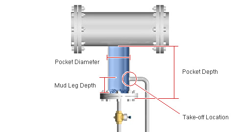
Sample guidelines for drip leg sizes are available in the table below. Also, the connection between the piping and drip leg should be set roughly 20 to 50 mm (¾ in to 2 in) from the bottom of the drip leg to help prevent dirt and scale within the condensate from flowing into the trap. With this type of setup, a blowdown valve is usually installed on the mud leg cover to allow for dirt removal.
Note: alternative drip leg sizing may be recommended depending on your location, e.g. according to "ASHRAE Fundamentals of Steam System Design". Contact TLV for more information.
Sample Guidelines for Drip Leg Dimensions
| Main Diameter (D) | Pocket Diameter (d1) | Pocket Depth (L) | Mud Leg Depth (L1) |
|---|---|---|---|
| ≤100 mm (4 in) | d1 = D | L ≥ d1 × 1.5 | 20-50 mm (¾-2 in) |
| 125-200 mm (5-8 in) | 100 mm (4 in) | ≥150 mm (6 in) | 20-50 mm (¾-2 in) |
| 250-300 mm (10-12 in) | 150 mm (6 in) | ≥275 mm (9 in) | 20-50 mm (¾-2 in) |
| ≥300 mm (12 in) | 200 mm (8 in) | ≥300 mm (12 in) | 20-50 mm (¾-2 in) |
When sizing a drip leg, design with sufficient volume for the mud leg portion, and also for the back-up portion between cycles. The collecting leg can be especially important on start-up operation where slugs of condensate from warming up the piping or condensate released from previously closed valves can be experienced.
| Properly Configured Drip Leg |
|---|
|
|
| Drip leg (drain pocket) size usually includes at least four factors: pocket diameter, pocket depth, mud leg depth, and take-off location. |
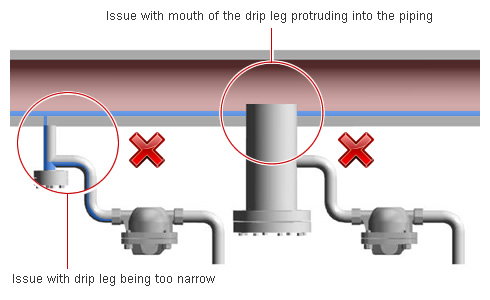
| Improperly Configured Drip Legs |
|---|
|
|
| Drip leg (drain pocket) size must be carefully selected and connections must be carefully set to allow for the smooth removal of condensate. |
Best Practice #4: Properly Remove Air and Condensate at End of Steam Line
At the end of steam distribution lines, it is important to remove the air that was initially present in the piping at start-up.
| Removing Air for Steam Lines |
|---|
|
|
| Steam lines require the installation of an air vent to prevent air from remaining trapped within the piping. |
Also, it is just as important to set up a drip leg for condensate drainage at the end of steam lines as it is for the other sections of the steam main.
| Installation of Trap at End of Steam Line |
|---|
|
|
| Installing a drip leg (drain pocket) at the end of the steam line will allow condensate to accumulate within the drip leg so that it be smoothly discharged. |
To summarize, efficient removal of condensate requires at least the following:
- Carefully choosinsteam trap locations
- Providing proper support and inclining the steam piping
- Configuring drip legs to allow for the smooth removal of condensate
- Properly removing air and condensate at end-of-lines
Because safety is an extremely important concern with steam piping configuration, always be certain to consult a steam specialist such as TLV when not sure how to proceed.

Over 50 calculations for steam, water, air and gas systems