- Home
- Steam Resources
- Steam Theory
- Steam Trap Selection: How Application Affects Selection
Basics of Steam Traps
Steam Trap Selection: How Application Affects Selection
Steps for Steam Trap Selection
Given the large variety of steam traps and their operating characteristics, users may encounter some difficulty when trying to select the correct trap to most effectively drain condensate from their steam applications.
Key trap selection considerations should include pressure and temperature ratings, discharge capacity, trap type, body material, and many other relevant factors. While it may seem daunting at first, this process can generally be separated into four easy-to-understand steps:
- Step 1: Determine discharge requirements of the steam trap application (e.g. hot or subcooled discharge), and select the matching trap type.
- Step 2: Select trap model according to operating pressure, temperature, orientation, and any other relevant conditions.
- Step 3: Calculate application load requirements and apply the trap manufacturer’s recommended safety factor.
- Step 4: Base the final trap selection on lowest Life Cycle Cost (LCC)
The first article of this three-part series will focus on how the steam trap application affects the steam trap selection process.
Steam Trap Applications
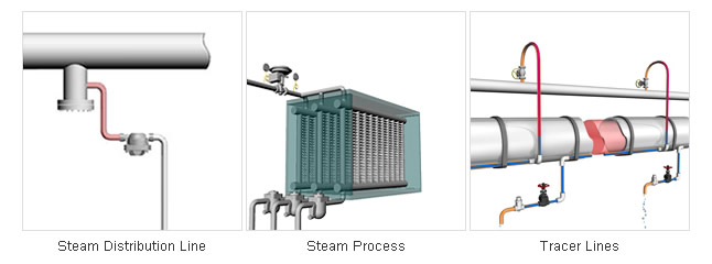
Steam traps are usually required to drain condensate from steam piping, steam-using process and comfort heating equipment, tracer lines, and drive-power equipment such as turbines. Each of these applications may require the steam trap to perform a slightly different role.
Different Steam Trap Applications
 |
|
Steam trap selection depends on the trap application. |
For Steam Distribution Piping
The role of steam distribution piping is to reliably supply steam of the highest reasonable quality to the steam-using equipment or tracing lines. One of the most important roles of steam traps on steam piping is to help prevent the occurrence of water hammer. This is done by selecting a trap that is designed to prevent condensate from pooling, which means traps with little to no subcooling of condensate (i.e. rapid near-to-steam temperature discharge) should be chosen.
For Steam-heated Equipment
Because the performance of steam-using process equipment and comfort heating equipment (e.g. air heaters) is directly tied to productivity and product quality, it's important to select a trap that helps shorten start-up time and does not allow condensate to pool into the equipment, causing uneven heating, low heat transfer, and other similar problems. Traps that continuously discharge condensate are typically recommended for these applications.
Such applications may also experience stagnant start-up air left over from condensed steam. As a result, an air venting function is also typically required in the trap to remove air and other non-condensable gases trapped in equipment and adjacent piping.
Also, some steam-heated equipment might experience problems from a modulating steam supply valve (e.g. control valve) that adjusts for heat demand and subsequently lowers the delivered steam pressure below that of the backpressure. When this phenomenon occurs, the condensate flow “stalls”, and a different type of drainage device is needed. Under stall conditions, a combination pump and trap supplied with a higher secondary pressure is needed to power the condensate discharge through the trap (e.g. PowerTrap®).
For more information on Stall, please read: What is Stall?
For Tracer Lines
Steam traps for tracer lines have different requirements because they are typically used with copper piping (because of its high thermal conductivity) to heat and maintain the fluidity of viscous fluids at temperatures below 100 °C (212 °F). A trap that has been designed to counter blockage from copper precipitate and that can efficiently use the sensible heat of steam/condensate is required.
For Power-drive Equipment
Power-drive equipment includes all turbines used in compressor, pump, or generator applications, but may also include steam hammers or wheels. In each power-drive application, condensate should be removed as quickly as possible for safe and effective operation, and should not pool inside the equipment to prevent damage.
Summary Table of Applications and Steam Trap Requirements
| Application | Trap Requirements | Product Examples |
|---|---|---|
| Steam Distribution Piping |
|
SS / FS Series |
|
Steam-heating Equipment No Stall |
|
|
|
Steam-heating Equipment Stall |
|
 GT Series |
|
Tracer Lines High Temp. |
|
   SS series / LV21 / P46S |
|
Tracer Lines Low Temp. |
|
 LEX3N |
|
Power-driven Equipment Positive Pressure |
|
  JH / FS series |
|
Power-driven Equipment Negative Pressure |
|
GT series |


* Provided as a general reference. Please consult a steam specialist such as TLV if you are unsure about trap selection or piping design.
After carefully evaluating the steam application discharge requirements and understanding which type of trap is most effective, the next step is matching steam trap specifications with operating conditions.
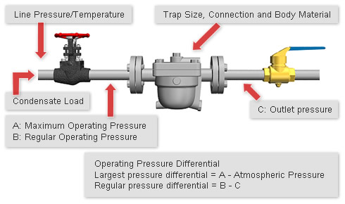
Operating Conditions Effect on Trap Specifications
System conditions determine the minimum trap specifications for pressure, temperature, discharge capacity, material, and connection type.
| Installed Piping and Piping Connections |
|---|
|
|
|
Installed piping influences connection type and sometimes the trap body material, so it important to make sure that the selected trap meets the piping requirements. For example, a trap may have a standard connection in NPT (national pipe thread), but the piping pressure requires socket weld. Additionally, other requirements include that the discharge capacity must be suitable for the maximum load at minimum differential pressure under all environmental conditions. |
Body Material
Trap body material is one of the first items to look at when selecting a trap. The material is selected based on the maximum operating temperature and pressure at the condensate discharge location (CDL), the surrounding environment, and requirements for longevity/ minimal maintenance. The material must also meet the pressure test and maximum pressure and temperature piping design specifications.
The materials used for the steam trap body, cover, and other pressure-resistant parts are no different from those used in other types of valves. Some examples are:
- Gray Cast Iron/ Ductile Cast Iron
- Carbon Steel
- Stainless Steel
The maximum applicable pressure and temperature of the body material are not necessarily equivalent to the maximum operating pressure and temperature of the trap. This is because the maximum operating pressure and temperature can be limited by the pressure/temperature resistance of other parts such as gaskets and other internal components.
In addition, different standards such as ASME or DIN can affect the maximum operating pressure / temperature of the trap material. For example, A126 cast iron has a maximum allowable pressure of 13 barg (190 psig) according to DIN standards, but 16 barg (250 psig) according to ASME standards. Also, stainless steel traps have recently become more and more popular because they are typically easier to maintain and offer a longer service life.
Sizing
A large number of steam users improperly select trap size based on the size of existing piping. However, trap size should closely match the size of the piping on the outlet side of the equipment that supplies condensate to the trap.
It is generally recommended to size condensate piping on the discharge side of equipment that supplies condensate to the steam trap according to the following table:
| Maximum Condensate Load | Equipment Outlet Piping Size |
|---|---|
| Less than 200 kg/h [440 lb/h] | 15 mm [1/2 in.] |
| 200 - 500 kg/h [440 - 1100 lb/h] | 20 mm [3/4 in.] |
| 0.5 - 1 t/h | 25 mm [1 in.] |
| 1 - 2 t/h | 32 mm [1 1/4 in.] |
| 2 - 3 t/h | 40 mm [1 1/2 in.] |
| 3 - 5 t/h | 50 mm [2 in.] |
| Over 5 t/h | 665 - 100 mm [2 1/2 - 4 in.] |
* Provided as a general reference. Please consult a steam specialist such as TLV if you are unsure about trap selection or piping design.
Generally, the trap should never be sized smaller than the equipment outlet piping because this can lead to waterlogging and ensuing damage and / or heating problems.
In addition, pipe sizing at the trap outlet should not be based on trap size, but instead should be designed to deliver the required flow rate and limit pressure loss for two-phase flow. For more information on this topic, please read: Condensate Recovery Piping
Connection Type
Most steam users typically require threaded (screwed), socket-welded, or flanged steam trap connections depending on the standard national, industry, or company codes and specifications.
Threaded connections cost much less than flanged connections to install, but need to be screwed-in during installation, meaning that either the trap outlet piping needs to remain disconnected or a union needs to be used to allow for easy trap replacement. On threaded connection steam traps, it is important that the trap threads follow official standards to help minimize poor connection sealing to the connected piping.
Traps with socket weld connections are generally preferred in some plants to limit the amount of steam leaks, but socket weld connections can be more difficult to remove during replacement, and may also have higher installation or maintenance costs. Additionally, some areas may have shortages of qualified welders, which can reduce the overall installation or repair efficiency.
Traps with flanged connections can be easily removed and replaced only if the new trap has the exact same size and face-to-face dimension. It is best to require a strict face-to-face dimension according to a trap manufacturer’s standard production item when specifying flanged traps on new construction projects.
| Example of Trap with Flanged Connections |
|---|
|
|
After selecting the trap specifications according to operating conditions and environment, the next step is evaluating the necessary discharge capacity that includes the safety factor, and selecting the most economical trap. For more info on these topics, please read part 2.