- Home
- Steam Resources
- Steam Theory
- Flash Steam
Basics of Steam
Flash Steam
Flash steam is a name given to the steam formed from hot condensate when the pressure is reduced.
Flash steam is no different from normal steam, it is just a convenient name used to explain how the steam is formed. Normal or “live” steam is produced at a boiler, steam generator, or waste heat recovery generator – whereas flash steam occurs when high pressure / high temperature condensate is exposed to a large pressure drop such as when exiting a steam trap.
High temperature condensate contains an excess of energy which prevents it from remaining in liquid form at a lower pressure. The result is that the excess energy causes a percentage of the condensate to flash.
| Flash Evaporation During Condensate Discharge |
|---|
|
|
| Condensate discharged out of the orifice of a trap partially evaporates (flash evaporation) due to the pressure difference (illustration). |
What causes Flash Steam?
Flash steam occurs because the saturation point of water varies according to pressure. For example, the saturation point of water is 100 °C (212 °F) at atmospheric pressure, but is 184 °C (363 °F) at 1.0 MPaG (145 psig).
So what happens when condensate kept under pressure at 184 °C (363 °F) is released to atmosphere? The condensate contains too much energy (enthalpy) to remain entirely liquid, and a portion of it evaporates, causing the temperature of the remaining condensate to drop to the saturation temperature (i.e., 100 °C or 212 °F if discharging to atmosphere). This phenomenon is known as flash evaporation.
In other words, when hot condensate is discharged into a lower pressure environment, its enthalpy (total energy) remains the same, but its saturation point drops (the temperature at which condensate can exist in both the liquid and gaseous state). To compensate for the excess amount of energy, part of the water molecules absorb the excess energy as latent heat and evaporate to form steam.
Additional Note
One of the first things that come to mind when visualizing flash steam are the steam clouds that can appear outside a non-sub-cooling trap releasing to atmosphere. These steam clouds can often be misinterpreted as a live steam leak when in fact they are simply comprised of flashed condensate with fine water droplets in suspension, caused by the flashing of hot condensate being released to atmosphere.
For a more detailed explanation, please read the article: Is My Trap Leaking Live Steam?.
Calculating the % Flash Steam Generated
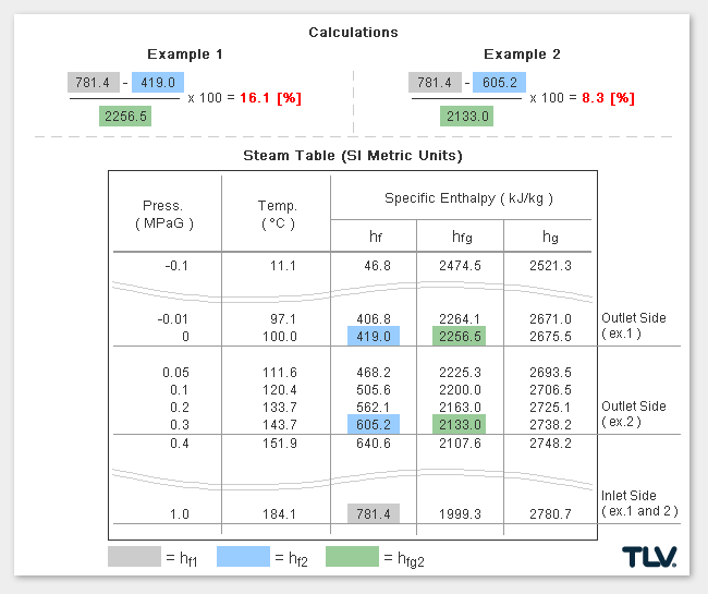
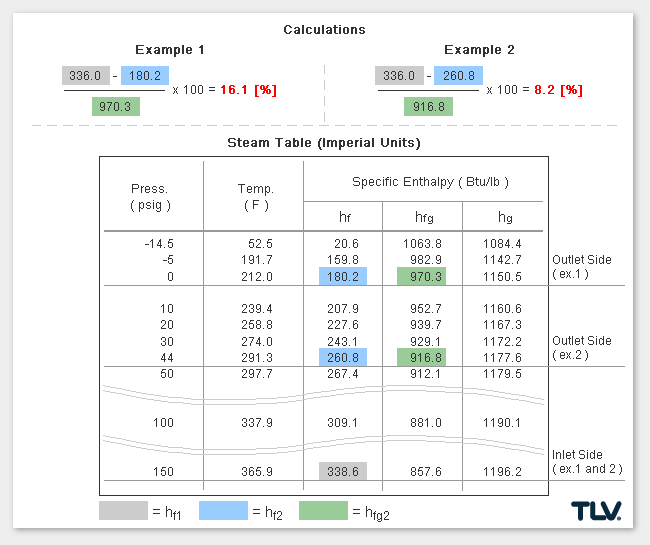
The % of flash steam generated (flash steam ratio) can be calculated from:

where:
- hf1 = Specific Enthalpy of Saturated Water at Inlet*
- hf2 = Specific Enthalpy of Saturated Water at Outlet
- hfg2 = Latent Heat of Saturated Steam at Outlet
* In traps designed to have a significant amount of sub-cooling of the condensate before discharge, the sensible heat of condensate at the trap inlet can be significantly lower than when estimated using inlet pressure saturated steam values.
As seen in the below examples, a higher % of flash steam is generated when condensate is discharged to atmosphere (example 1) compared to when it is discharged into a closed return system (example 2):
Tip
Use TLV's online Engineering Calculator for quick and accurate calculation of Flash Steam Generated by Hot Condensate.
Volume of Flash Steam generated
Steam is much less dense than water, which means that a small increase in the percentage of flash steam generated can appear as a large increase in volume of steam generated. The animation below shows the difference in ratio of steam to condensate for examples 1 and 2 (see above) when applied to condensate return piping.
|
|
| The greater the pressure difference, the larger the amount of flash steam generated at discharge. |
To understand with great detail, the specific volume of condensate at 100 °C (212 °F) is 0.00104 m3/kg (0.0167 ft3/lb), and the specific volume of atmospheric steam is 1.67 m3/kg (26.8 ft3/lb). When high temperature condensate at 1.0 MPaG (145 psig) is discharged to lower pressure such as atmosphere, 16.1% by mass of that condensate flashes into steam. The resulting volumetric ratio can be contrasted as follows:
Calculating Flash to Condensate Ratio (Metric)
- Condensate Volume: (1 - 16.1%) x 0.00104 m3/kg = 0.000873 m3/kg
- Steam Volume: 16.1% x 1.67 m3/kg = 0.269 m3/kg
- Flash to Condensate Ratio: 0.269 m3/kg / 0.000873 m3/kg = 308:1
Calculating Flash to Condensate Ratio (Imperial)
- Condensate Volume: (1 - 16.1%) x 0.0167 ft3/lb = 0.0140 ft3/lb
- Steam Volume: 16.1% x 26.8 ft3/lb = 4.31 ft3/lb
- Flash to Condensate Ratio: 4.31 ft3/lb / 0.0140 ft3/lb = 308:1
What to Do With Flash Steam?
The vapor cloud formed by flash steam is a natural by-product of condensate discharge. Since flash steam is of the same quality as live steam, modern facilities often try to reuse significant amounts of flash steam whenever possible.
Reusing flash steam generated by a higher pressure system for use in a lower pressure system can enable considerable energy savings in addition to improving a plant's working environment by reducing vapor clouds. When trying to implement a waste heat management system, condensate recovery systems and flash steam recovery systems are often evaluated together as a pair.
| Example of Flash Steam Recovery System |
|---|
|
|
| Flash steam from a high pressure system is recovered into a flash tank and reused as steam in a low pressure system. |

Over 50 calculations for steam, water, air and gas systems