- Home
- Steam Resources
- Steam Theory
- How Disc Traps Work: A Look at their Mechanism and Merits
Basics of Steam Traps
How Disc Traps Work: A Look at their Mechanism and Merits
Thermodynamic type steam traps are valued for their compact size and versatility over a wide pressure range. They can have a simple construction, and operate in either horizontal or vertical positions. These characteristics make thermodynamic steam traps a favored choice for a wide variety of tracing, drip, and certain light process steam applications.
Two Types: Disc and Impulse
There are two basic categories of thermodynamic steam traps: Thermodynamic Disc and Thermodynamic Impulse. Of the two, disc traps are most commonly used, perhaps because impulse traps can leak pilot steam, and may fail in the presence of even a slight amount of dirt blocking the pilot channel. For these reasons, this article will only cover disc-type traps.
| Disc-type and Impulse-type Steam Traps |
|---|
|
|
| In disc-type traps, the valve opens and closes according to changes in the forces acting on the flat disc valve. In impulse-type traps, the movement of the piston disc controls the flow. The stem can be adjusted to increase or limit flow. Both disc-type and impulse-type thermodynamic traps discharge condensate intermittently. |
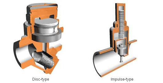
In a thermodynamic disc steam trap, the flow of condensate is controlled by a circular shape valve head (valve disc) opening and closing against the valve seat. The valve disc is disconnected from all other parts of the trap, and rests on top of the valve seat.
| Disc-type Steam Trap |
|---|
|
|
| The valve opens when the valve disc rises off the valve seat. |
The valve seat is comprised of two concentric rings (seat rings): an inner ring and an outer ring. The inner ring separates the fluid inlet hole from the outlet hole(s) and prevents the short-circuiting of steam to the outlet. The outer ring controls the leakage of steam from the pressure chamber above the disc to the outlet.
Benefits of Thermodynamic Disc Traps
| Benefit | Reason |
|---|---|
| Easy to Install | Compact |
| Can be installed in either the vertical or horizontal position | |
| Easy Selection & Storage | A single trap can cover a large range of pressures |
| Can be used on superheated steam | No water seal needed |
| Highly resistant to damage from freezing | Little water remains inside trap body |
| Low Initial Cost | Relatively simple construction |
Limitations of Thermodynamic Disc Traps
| Limitation | Reason |
|---|---|
| Shorter service life | Operating mechanism causes wear of the valve trim |
| Greater steam loss | No water seal can lead to steam loss during condensate discharge |
| Sensitive to environmental conditions | Rain and/or cold air can lead to no load actuation |
| Noisy | Operating mechanism causes near instant release of a high volume of condensate, which creates more noise than many other types of steam traps |
Operating Mechanism of Thermodynamic Disc Traps
Thermodynamic disc steam traps have an intermittent, cyclical operating characteristic. The valve mechanism — comprised of a disc and seat rings — opens to discharge condensate for a few seconds; and then closes for a generally longer period until a new discharge cycle begins.
The opening and closing action of thermodynamic disc traps is caused by the difference in the forces acting on the bottom and top sides of the valve disc. These forces are essentially based on variations in kinetic and pressure energy of the typical fluids involved: air, condensate, and steam.
At start-up, incoming fluids consisting of air, and/or condensate (and even sometimes steam) at line pressure exert an Opening Force (Lifting Force) on the bottom of the valve disc; thereby causing it to rise and open. This Opening Force elevates the disc off the seat to allow condensate flow. The next section explains how the disc mechanism closes after it is opened.
Situation 1: From the Open to the Closed Position (Thermodynamic Explanation)
When in the open position, there are two main forces that act on the disc valve: steam in the pressure chamber on top of the disc, and steam racing across the underside of the disc. This steam acting to open and close the valve is known as Control Steam.
| Disc Valve Closing |
|---|
|
|
| When steam rapidly flows under the valve disc, the pressure under the disc decreases. The valve disc is then "pushed" onto the valve seat because of the greater pressure within the chamber. This closes the valve. |
| Bernoulli Forces at Work |
|---|
|
|
| Bernoulli's principle says that an increase in the speed of a fluid is accompanied by a decrease in pressure. |
Control Steam can be either flash steam or live steam. It is flash steam when condensate enters the trap and undergoes a phase change due to a reduction in pressure. It can be live steam in cases where condensate load is small, or if the design may be compromised and not guard against unnecessary steam loss. The best designs minimize or eliminate live steam use, and operate using flash steam wherever possible.
Control Steam within the pressure chamber exerts a downward force on the top of the valve disc as a result of its Pressure x Area. Control steam on the underside of the disc causes a pressure drop under the disc because of its high velocity (as long as the disc is in the open position).
The valve is designed to close on flashing condensate near-to-steam temperature, which occurs once the accumulated condensate is discharged. When the Closing Force is big enough to overcome the Opening (Lifting) Force, the valve closes.
| Decrease in Pressure Within the Chamber |
|---|
|
|
| Radiant and other heat losses cause a decrease in the pressure within the chamber, which eventually causes the disc to lift off its seat, discharging condensate. |
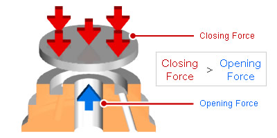
| Forces Acting on Disc Valve |
|---|
|
|
| There are two main forces acting on the disc, the Closing Force and the Opening (Lifting) Force. |
Situation 2: From the Closed to the Open Position (Thermodynamic Explanation)
When in the closed position, steam inside the pressure chamber exerts a Closing Force on the valve disc and seals the pressure chamber shut.
Over time, the pressure chamber loses Closing Force (i.e. pressure) from conduction losses caused by the inflow of condensate, radiant or convection heat losses caused by environmental conditions, and by any leakage that occurs through the outer seat ring (such as if worn-out or otherwise compromised). When the Closing Force becomes weaker than the Opening Force (Lifting Force), the disc elevates and discharges condensate again.
In the closed position, the Closing Force is determined solely by the steam pressure acting on the top of the disc. The Opening Force is determined by inlet pressure on the underside area of the disc. That Opening Force area becomes reduced when the valve is closed, essentially confined to the inlet port diameter.
| Worn Valve Disc and/or Valve Seat |
|---|
|
|
| When the valve disc and/or the valve seat are worn-out or otherwise compromised, the pressure within the chamber drops more rapidly, causing the valve to open and close more frequently. |
As a simplified explanation, a greater surface area on the top of the valve disc than on the bottom creates a significant force difference, and can provide tight closure. This difference in surface areas prevents the valve from opening even if the pressures exerted on both sides of the disc are similar, which is why some manufacturers employ wider diameter discs for more effective sealing. When the Closing Force becomes weaker than the Opening Force, the valve opens and a new discharge cycle begins.
Situation 3: Open and Closing with Air in the Steam System (Aerodynamic Explanation)
At least on start-up, the vapor stream that enters the trap can also be comprised of significant amounts of air. Air and steam vapors act similarly in creating the Closing Force to shut a thermodynamic disc trap. However, unlike steam, air does not condense at environmental conditions to allow the disc to open; and common disc traps can lock shut. This condition is known as Air Binding. Air binding can be a typical event creating a drainage failure (cold trap), and there are several methods to deal with this phenomenon. For related information, please see: Air Binding.
| Air Binding in Disc Traps |
|---|
|
|
| Since air does not condense like steam, the pressure within the chamber does not drop and the Opening Force cannot overcome the Closing Force, preventing condensate discharge. |
Disc trap manufacturers deal with air binding issues in a variety of ways. Some create intentional air leakage pathways across the disc. Others incorporate a separate blowdown valve on a strainer to be used at start-up to help vent vast amounts of air. The differences in design may be evident by referring to functional steam loss values, which can represent steam loss during normal operation. If a trap already has a built-in leak pathway, its sealing capability may be compromised from the beginning.
| Usage of a Leakage Path |
|---|
|
|
| If a leakage path is created, steam as well as air is discharged, wasting energy. The valve also opens and closes more frequently, which increases wear and shortens the life of the trap. |
Advanced Thermodynamic Disc Traps
Certain advanced thermodynamic disc traps have a built-in thermostatic air vent that works to remove air on start-up. Disc traps with this innovative feature are thermodynamic disc traps with thermostatic vents.
On start-up, the thermostatic ring holds the disc off the seat until the air is vented out of the system. As air is released, the fluid temperature rises allowing the thermostatic ring to expand and move downward to the lower resting position. From this point forward, the thermodynamic disc operation of the valve performs normally, but with the benefit that the valve mechanism does not need to have built-in leakage pathways to handle air.
Example of an Advanced Thermodynamic Disc Trap
| To counter problems such as air binding, certain disc traps are fit with a bimetal ring to forcefully open the valve. Other innovations include improved sealing between the valve disc and valve seat, the inclusion of a strainer, and facilitating maintenance through a replaceable module. |
The benefit of this advanced design is that the valve mechanism can be made to seal as tightly as possible, because it has just one clear task: to shut tightly against steam leakage.
Advanced thermodynamic models may also incorporate other features to lower life cycle costs. Typical improvements include: full Y-strainers to increase reliability, blowdown valves for start-up operation, and completely replaceable internals to reduce maintenance cost and time required for repair.