- Home
- Steam Resources
- Steam Theory
- How Mechanical Traps Work: A Look at their Mechanism and Merits
Basics of Steam Traps
How Mechanical Traps Work: A Look at their Mechanism and Merits
Mechanical traps are steam traps that operate on the principle of specific gravity (specifically the difference in the specific gravities of water and steam), unlike other types of steam traps that rely on temperature change or velocity/phase change. In mechanical traps, the valve opens and closes due to the movement of a float that rises and sinks with the flow of condensate.
Mechanical traps are able to operate in precise response to the flow of condensate without their performance being compromised by most external factors. This is one of their distinct advantages over thermostatic and thermodynamic steam traps, whose performances can be affected by external factors such as rain, wind, or even insulation.
Two Designs: Float and Inverted Bucket
There are two main types of mechanical steam traps: float traps and inverted bucket traps. Float traps typically utilize a sealed spherical float, while inverted bucket traps utilize a buoyant, cylindrical cup turned upside-down.
Buoyancy is the key force operating at the core of both types of mechanical traps, but their structures and principles of operation are quite different.
Float Type
In float traps, the position of the float is affected directly by the level of condensate in the trap. The float responds to condensate flow, opening and closing the valve to compensate accordingly.
There are two basic designs used for float traps: lever float and Free Float®.
In lever float designs, a float is attached to a lever that controls the valve. As condensate enters the trap, the float becomes buoyant and moves the lever, causing the trap valve to open. However, due to the limited movement of the lever arm, the valve head often remains in the path of condensate flow, which may result in an extra pulling force acting to close the valve during high flow conditions.
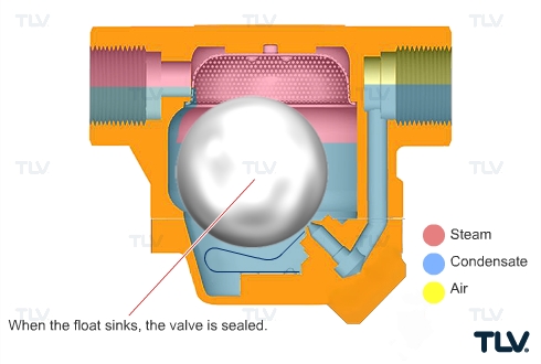
In TLV Free Float® traps, the float is not attached to a lever, and the float itself serves as the valve for the trap. A Free Float® is able to independently rise away from the orifice, allowing condensate to be drained free of obstruction. Additionally, the natural rotation of the Free Float® allows for an almost infinite number of contact points to seal the orifice, significantly reducing localized valve wear.
Inverted Bucket Type
In inverted bucket steam traps, the bucket within the trap is attached to a lever that opens and closes the trap valve in response to the bucket’s motion. When steam or air flows into the underside of the inverted bucket and condensate surrounds it on the outside, the steam causes the bucket to become buoyant and rise. In this position, the bucket will cause the trap valve to close. There is a vent hole in the top of the bucket that allows a small amount of the vapor to be released into the top of the trap, where it is discharged downstream. As vapor escapes through the vent hole, condensate starts to fill the inside of the bucket, causing it to sink and allowing the lever to open the trap valve and discharge condensate (along with any vapor held in the trap).
| Inverted Bucket Steam Trap |
|---|
|
|
Continuous Drainage: A Significant Advantage of Float Type Traps
One key difference in the operation of float traps and inverted bucket traps is the type of condensate drainage they provide; float traps provide continuous drainage, whereas inverted bucket traps provide intermittent drainage.
| Float Traps Offer Continuous Drainage |
|---|
|
|
In steam traps that continuously drain condensate, the float rises and falls based on the condensate load entering the trap, allowing the valve to automatically adjust to the level of condensate in the trap. When condensate enters, the valve opens just enough to drain the condensate, closing once the flow of condensate ceases. This allows the trap to respond quickly to fluctuations in condensate load.
| Inverted Bucket Traps Offer Intermittent Drainage |
|---|
|
|
On the other hand, in steam traps that drain intermittently, condensate is not drained until a significant amount of vapor is vented from the bucket, thereby triggering the bucket to sink and the valve to open. Consequently, when the valve is closed, it can shut completely, with no condensate drained until a certain amount of steam is vented from the inside of the bucket.
The flow of condensate from equipment and steam lines is generally continuous, regardless of how a particular steam trap operates. As such, in steam traps that drain intermittently, condensate will accumulate within the trap for as long as the valve remains closed.
Trap Selection Affects Operation in Low-Condensate Systems
Steam traps are a necessity in any system where condensate forms, even if it forms in very small volumes, such as in systems using superheated steam. Because of this, it is important to understand how steam traps operate in environments where condensate loads may be extremely low.
In superheated systems, there is often little condensate. During such operations, there may not be sufficient water inside an inverted bucket trap to create buoyancy. As a result, the bucket falls to the bottom of the trap, leaking large amounts of superheated steam. This is not only costly, but can also elevate return backpressure.
Float traps are also affected during use in superheated systems. In lever float traps, the valve head is very close to the seat. Low flow operation may cause condensate to flow through the valve at extremely high velocities, causing erosion of valve components known as “wire draw.” A Free Float®, however, pivots off the top of the seat during low flow service. Since the valve head is not directly in the flow path, wire draw is prevented even under low flow conditions.
| Float Traps in Low-Condensate Systems |
|---|
|
|
| Inverted Bucket Traps in Low-Condensate Systems |
|---|
|
|
Orifice Number Indicates Maximum Operable Pressure
One notable characteristic of mechanical traps is that there are different orifice sizes based on pressure differential available for each model. The orifice size is designed to match the maximum operating pressure (PMO) of the trap.
It is important to understand that if a trap is used above its PMO, the trap valve may not be able to open. In this situation, known as “pressure block,” the trap remains closed, and condensate will not be drained.
To learn more about mechanical traps and orifice numbers, please read: