- Home
- Steam Resources
- Steam Theory
- Traps and Orifices Part 2
Basics of Steam Traps
Traps and Orifices Part 2
The discussion on orifices in Traps and Orifices Part 1 focused on why the diameter of a trap orifice (valve seat) is much smaller than the diameter of the connected piping. In Part 2, we will discuss the significance of the trap orifice number.
What is an Orifice No.?
The higher the trap orifice number, the smaller the diameter of the orifice. At first glance, this may seem counter-intuitive, but a closer look reveals the reasoning behind this system.
In TLV steam traps, the orifice number indicates the maximum differential pressure in kg/cm² (bar) at which the steam trap will discharge condensate. For example, a No. 10 orifice is rated for 10 kg/cm² (10 bar, 150 psi). The higher this number is, the higher the pressure at which the orifice can be used to drive condensate through it. However, in order to achieve higher operating pressure differentials, a smaller opening is required, which results in a lower discharge capacity for a given operating differential pressure.
Forces Acting to Close and Open the Valve
When we think about the size of an orifice, we must consider two of the forces at work inside the Free Float® trap, namely the force that acts to open the valve and the force that acts to close the valve.
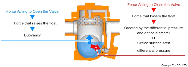
The mechanism that causes the Free Float® trap to operate is the force of buoyancy.
Buoyancy causes the float (which is also the valve itself) to rise, and after the float rises up off the valve seat, the valve is in the open position. In other words, the force of buoyancy is the force that acts to open the valve. If we assume that the specific weight of condensate is a constant, then the buoyancy of the float is determined by the volume of the submerged part of the float. The force of buoyancy is therefore at its highest value when the float is completely submerged, and given that the same float is being used, it is not possible to achieve a stronger force acting to open the valve than this.
In contrast, the force acting to close the valve is a force that is created by the diameter of the orifice and the difference between the pressures in front of and behind the orifice. An example of this that is familiar to many of us is when the water is draining out of a bathtub that uses a drain plug. If the plug gets too close to the drain as water is being drained out, the plug is sometimes sucked back into place on the drain, closing off the flow of water. A force identical to this is at play inside a Free Float® trap.
The force is represented as pressure differential x surface area, so if the orifice diameter is a constant, then the larger the difference in pressures in front of and behind the orifice (the differential pressure), the stronger the force acting to close the valve. Conversely, if the differential pressure is fixed, then the larger the orifice diameter, the stronger the force acting to close the valve.
|
| Fig. 1 If the orifice diameter is constant, then the larger the operating differential pressure, the stronger the force acting to close the valve. |

|
| Fig. 2 If the differential pressure is constant, then the larger the orifice diameter, the stronger the force acting to close the valve. |
Orifice No. Selection
While the force acting to open the valve has a maximum value (determined by the size of the float), the force acting to close the valve can vary depending on the operating pressure. Condensate cannot be evacuated if this force is too great, which can cause the valve to remain in the closed position. In order to overcome this limitation imposed by the operating pressure, a variety of orifice no.’s are offered for use with different maximum operating pressures.
Summary
| Objective | To Increase the Discharge Capacity | To Increase the Maximum Operating Pressure |
|---|---|---|
| Method | Increase the orifice diameter (smaller orifice number) | Decrease the orifice diameter (larger orifice number) |
| Consequence | Reduced maximum operating pressure | Reduced discharge capacity |
In short, even for the same trap model, there are selection options to be made between maximum operating differential pressure and discharge capacity. Reducing the maximum operating pressure allows us to achieve a greater discharge capacity at any given differential pressure, while reducing the maximum discharge capacity provides a higher maximum operating pressure.