- Home
- Steam Resources
- Steam Theory
- Condensate Recovery Piping
Condensate Recovery
Condensate Recovery Piping
Condensate that is discharged from steam traps is handled in one of two ways. It is either drained out of the system to sewer, which can result in wasted heat energy and water, or it flows into piping to be transported elsewhere, ideally for recovery.
Piping for Two-Phase Flow
The piping used to transport condensate is typically called “condensate recovery piping” or “condensate return piping”. The design sizing of such piping requires significant specialization because condensate recovery piping collecting from steam traps must be designed for two-phase flow. The design should not be based on calculations for piping that transports only water because these are not valid for two-phase flow.
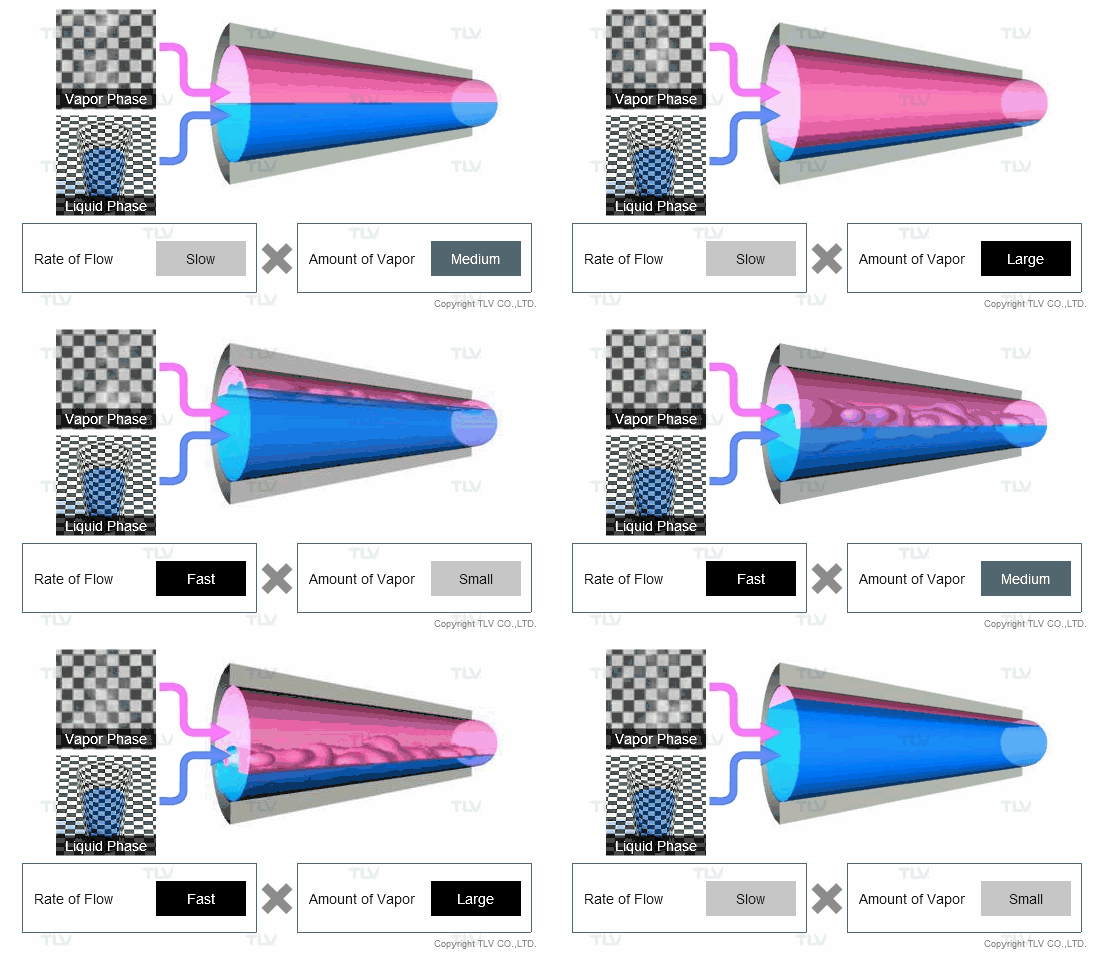
Two-phase flow refers to flow in which vapor such as steam (either flash steam, live steam, or a mix of both) flows through piping together with liquid condensate. Although flowing together, this does not necessarily mean that the liquid and vapor are flowing in distinct separate layers. The flow pattern within the piping can also be mixed, as illustrated in the below animation.
|
Piping Considerations for Flow Patterns of Two-Phase Flow |
|---|
|
|
| The flow pattern inside condensate recovery piping varies greatly according to pipe size, flow rates, and steam/condensate volume proportions. |
Why is Steam Present in Condensate Recovery Piping?
Considering steam vapor when designing condensate recovery piping may at first seem counterintuitive, but is in fact necessary.
This is due to a phenomenon known as flash evaporation, which occurs when high temperature condensate formed at a high pressure is suddenly introduced into a low pressure system such as a condensate recovery line on the outlet side of a steam trap. Upon discharging through a steam trap, the high temperature condensate from the inlet is now subjected to a lower pressure and therefore contains too much heat energy to remain in the liquid phase. This excess sensible heat causes part of the condensate to instantly evaporate or “flash” back into steam. The term “flash steam” simply describes the way the steam was created; it is otherwise no different from “live steam.”
For more on flash steam evaporation, please read the article:
|
How Flash Steam Amount Influences Pipe Size |
|---|
|
|
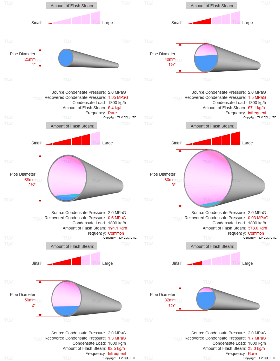
| As the differential pressure across the trap increases, a larger percentage of condensate flashes to steam, requiring the use of larger-sized condensate return lines. |
At lower recovery line pressures, the specific volume of saturated steam can be more than 1,000 times that of saturated condensate. In many instances, this volumetric ratio can be more than 90 to 1. The volumetric proportion of steam to condensate will therefore vary depending on the amount of flash steam created or “flashing rate”, and this in turn can greatly affect pipe sizing design requirements.
If no flash steam occurs, the piping design velocity and pressure drop calculations can be similar to those for single-phase water transport piping. However, a “no flash” situation can only occur if the condensate is significantly subcooled to a temperature less than the saturated water temperature associated with the recovery line pressure. If the amount of flash steam is large, the required piping size becomes almost identical to that of steam piping. As such, designing condensate recovery piping first requires calculating the amount of flash steam and then sizing the pipe to accommodate the specific volume ratios for both water and steam flow, with their respective required velocity and pressure drop design parameters.
|
Example of Condensate Recovery Piping |
|---|
|
|
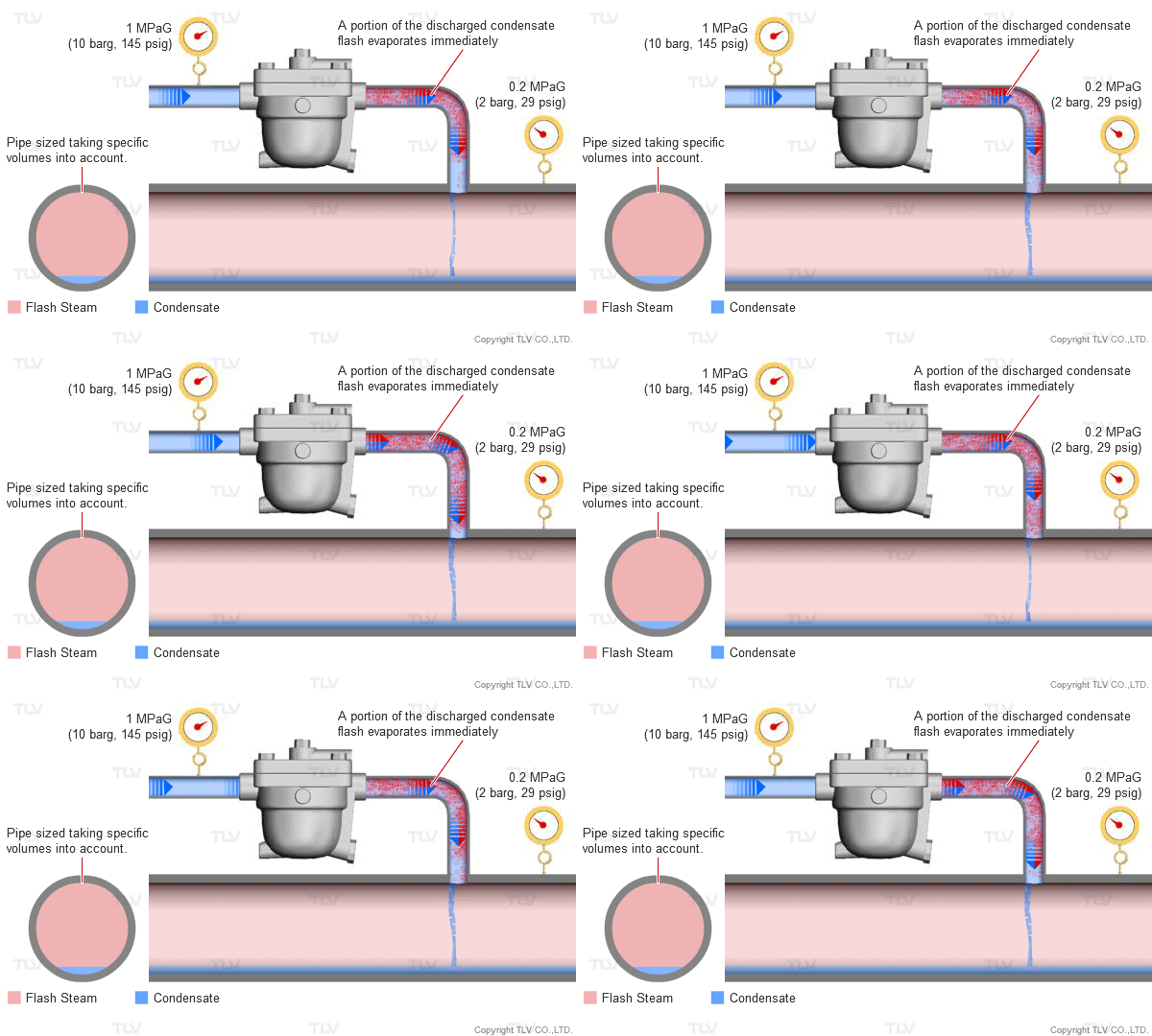
| The flash steam ratio (by mass) for an inlet pressure of 1 MPaG [10 barg, 145 psig] and an outlet pressure of 0.2 MPaG [2 barg, 29 psig] is roughly 10%, or 1 : 10, flash steam to condensate . However, when specific volumes are compared, the volume ratio is about 62 : 1. In terms of occupied space, the inside of the condensate return line is therefore often mostly comprised of flash steam. |
|
Example of Condensate Recovered Using a Flash Tank |
|---|
|
|
|
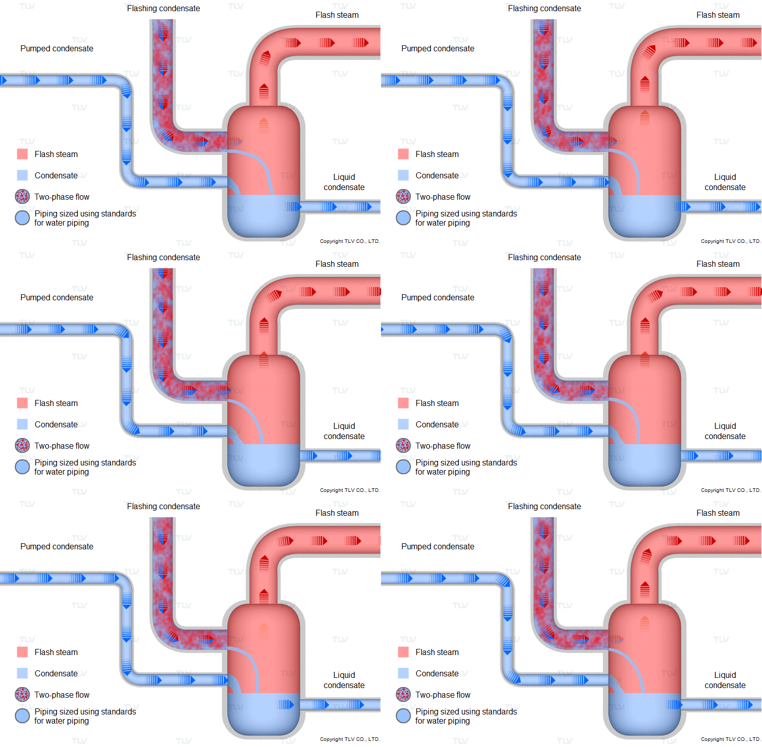
A flash tank can be installed to recover and reuse flash steam. The flash tank allows for the separation of steam and condensate and then each can be transported using separate piping. In such a case, design the liquid condensate piping using standards for water distribution piping. There are multiple benefits to installing a flash tank. The flash steam can be used to supply low pressure equipment or be used for pre-heating, while the hot, non-flashing liquid condensate can be returned to the boiler where its heat is reused, increasing overall efficiency. |
High energy condensate can be used either at the boiler or some other point along the transportation line. If the flash steam energy can be used locally, the system designer can weigh the relative benefits of either a) returning condensate to the boiler, using smaller size piping but requiring a pumping system, or b) using larger piping to return the condensate without a localized flash system. Transporting flashing condensate over large distances requires certain design constraints for gravity return to mitigate the introduction of water hammer.
For more information, read:
- Water Hammer in Condensate Transport Piping
- Mitigation of Water Hammer in Vertical Flashing Condensate Transport Piping
Design Methods for Condensate Recovery Piping
As previously stated, TLV recommends sizing condensate recovery piping based on the amount of flash steam and liquid condensate that can be present in a return piping system.
We recommend using specific volumes of each phase to determine volume ratios of condensate and steam at a given pressure and then calculating a maximum allowable flow velocity. You should then size piping based on the allowable velocity and pressure drop parameters.
Other factors that may be considered when sizing condensate recovery piping are:
- The presence of live steam in the piping from leaks or bypassed traps
- The long term effects of corrosion or mud in the system, possibly reducing the internal cross-section piping area
Both of these may have the effect of increasing velocity, pressure drop, and system back pressure. For a more detailed explanation of the calculation for sizing condensate recovery piping, readers can refer to TLV’s technical handbooks entitled “Condensate Drainage and Recovery” and “Efficient Use of Process Steam”.


